RF-10 High Frequency PCB: 60mil Taconic Microwave PCB with Low Loss and High DK
(Printed Circuit Boards are custom-made products, the picture and parameters shown are just for reference)
Product Overview
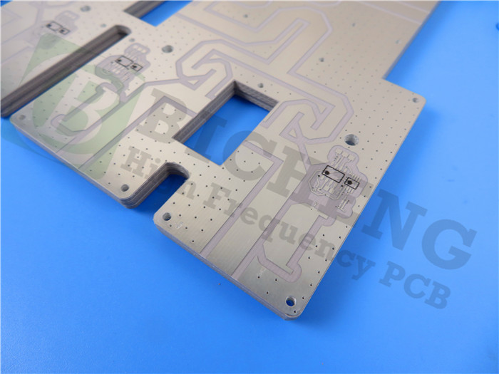
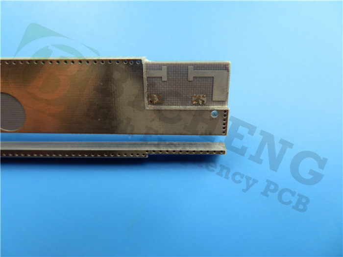
Introducing the RF-10 High Frequency Printed Circuit Board, a robust solution crafted from a 60mil RF-10 substrate. This double-layer PCB is designed for microwave applications, featuring a large area of immersion gold and partial green solder mask. Key specifications include:
Thickness: 60mil (1.524mm)
Copper Weight: Finished with 1oz copper on both sides.
Fabrication Standards: Manufactured per IPC 6012 Class 2 using supplied Gerber data.
Packaging: Boards are packed in batches of 25 for secure shipment.
PCB Specifications
| PCB SIZE | 90 x 100mm=1up |
| BOARD TYPE | Double sided PCB |
| Number of Layers | 2 layers |
| Surface Mount Components | YES |
| Through Hole Components | NO |
| LAYER STACKUP | copper ------- 17um(0.5 oz)+plate TOP layer |
| RF-10 1.524mm | |
| copper ------- 17um(0.5 oz) + plate BOT Layer | |
| TECHNOLOGY | |
| Minimum Trace and Space: | 4 mil / 4 mil |
| Minimum / Maximum Holes: | 0.3 mm / 4.0 mm |
| Number of Different Holes: | 5 |
| Number of Drill Holes: | 211 |
| Number of Milled Slots: | 5 |
| Number of Internal Cutouts: | 3 |
| Impedance Control: | no |
| Number of Gold finger: | 0 |
| BOARD MATERIAL | |
| Glass Epoxy: | RF-10 1.524mm |
| Final foil external: | 1.0 oz |
| Final foil internal: | N/A |
| Final height of PCB: | 1.6 mm ±0.16 |
| PLATING AND COATING | |
| Surface Finish | Immersion Gold, 89% |
| Solder Mask Apply To: | Top layer |
| Solder Mask Color: | Green |
| Solder Mask Type: | LPI |
| CONTOUR/CUTTING | Routing |
| MARKING | |
| Side of Component Legend | N/A |
| Colour of Component Legend | N/A |
| Manufacturer Name or Logo: | N/A |
| VIA | Plated through hole(PTH), minimum size 0.3mm. |
| FLAMIBILITY RATING | 94V-0 |
| DIMENSION TOLERANCE | |
| Outline dimension: | 0.0059" |
| Board plating: | 0.0029" |
| Drill tolerance: | 0.002" |
| TEST | 100% Electrical Test prior shipment |
| TYPE OF ARTWORK TO BE SUPPLIED | email file, Gerber RS-274-X, PCBDOC etc |
| SERVICE AREA | Worldwide, Globally. |
Typical Applications
The RF-10 PCB is suitable for a variety of high frequency applications, including:
Aircraft Collision Avoidance Systems
GPS Antennas
Microstrip Patch Antennas
Passive Components (filters, couplers, power dividers)
Satellite Components
Why Choose Us?
1.Certified Quality: ISO9001, ISO14001, IATF16949, ISO13485, and UL certified.
2.Expertise: Over 18 years of experience in high frequency PCB manufacturing.
3.Flexible Ordering: Small quantity orders available; no minimum order quantity required.
4.Dedicated Team: Committed to passion, discipline, responsibility, and honesty.
5.Timely Delivery: Over 98% on-time delivery rate with a customer complaint rate of less than 1%.
6.Extensive Facilities: 16,000㎡ workshop with a monthly output of 30,000㎡ and 8,000 types of PCBs.
7.Support for Innovation: Comprehensive PCB capabilities to support your research, development, sales, and marketing efforts.
8.IPC Standards: Compliant with IPC Class 2 and Class 3 standards.
Typical Values of RF-10
| RF-10 Typical Values | |||||
| Property | Test Method | Unit | Value | Unit | Value |
| Dk @ 10 GHz | IPC-650 2.5.5.5.1 Mod. | 10.2 ± 0.3 | 10.2 ± 0.3 | ||
| Df @ 10 GHz | IPC-650 2.5.5.5.1 Mod. | 0.0025 | 0.0025 | ||
| TcK† (-55 to 150 °C) | IPC-650 2.5.5.6 | ppm/°C | -370 | ppm/°C | -370 |
| Moisture Absorption | IPC-650 2.6.2.1 | % | 0.08 | % | 0.08 |
| Peel Strength (1 oz. RT copper) | IPC-650 2.4.8 (solder) | lbs/in | 10 | N/mm | 1.7 |
| Volume Resistivity | IPC-650 2.5.17.1 | Mohm/cm | 6.0 x 10⁷ | Mohm/cm | 6.0 x 10⁷ |
| Surface Resistivity | IPC-650 2.5.17.1 | Mohm | 1.0 x 10⁸ | Mohm | 1.0 x 10⁸ |
| Flexural Strength (MD) | IPC - 650 - 2.4.4 | psi | 14,000 | N/mm2 | 96.53 |
| Flexural Strength (CD) | IPC - 650 - 2.4.4 | psi | 10,000 | N/mm2 | 68.95 |
| Tensile Strength (MD) | IPC - 650 - 2.4.19 | psi | 8,900 | N/mm2 | 62.57 |
| Tensile Strength (CD) | IPC - 650 - 2.4.19 | psi | 5,300 | N/mm2 | 37.26 |
| Dimensional Stability | IPC-650 2.4.39 (After Etch) | % (25 mil-MD) | -0.0032 | % (25 mil-CD) | -0.0239 |
| Dimensional Stability | IPC-650 2.4.39 (After Bake) | % (25 mil-MD) | -0.0215 | % (25 mil-CD) | -0.0529 |
| Dimensional Stability | IPC-650 2.4.39 (After Stress) | % (25 mil-MD) | -0.0301 | % (25 mil-CD) | -0.0653 |
| Dimensional Stability | IPC-650 2.4.39 (After Etch) | % (60 mil-MD) | -0.0027 | % (60 mil-CD) | -0.0142 |
| Dimensional Stability | IPC-650 2.4.39 (After Bake) | % (60 mil-MD) | -0.1500 | % (60 mil-CD) | -0.0326 |
| Dimensional Stability | IPC-650 2.4.39 (After Stress) | % (60 mil-MD) | -0.0167 | % (60 mil-CD) | -0.0377 |
| Density (Specific Gravity) | IPC-650-2.3.5 | g/cm3 | 2.77 | g/cm3 | 2.77 |
| Specific Heat | IPC-650-2.4.50 | J/g°C | 0.9 | J/g°C | 0.9 |
| Thermal Conductivity (Unclad) | IPC-650-2.4.50 | W/M*K | 0.85 | W/M*K | 0.85 |
| CTE (X -Y axis) (50 to 150 °C) | IPC-650 2.4.41 | ppm/°C | 16-20 | ppm/°C | 16-20 |
| CTE (Z axis) (50 to 150 °C) | IPC-650 2.4.41 | ppm/°C | 25 | ppm/°C | 25 |
| Flammability Rating | Internal | V-0 | V-0 | ||
Explore the RF-10 High Frequency PCB today for reliable performance in your microwave applications! For inquiries or to request a quote, please feel free to contact us.
